



Overview
Aggiungi comunicazione Narrowband al tuo progetto con l'MKR NB 1500. È la scelta perfetta per dispositivi in luoghi remoti senza connessione Internet, o in situazioni in cui non è disponibile energia, come nelle distribuzioni sul campo, nei sistemi di misurazione remota, nei dispositivi alimentati a energia solare o in altri scenari estremi.
Il processore principale della scheda è un Arm® Cortex®-M0 a bassa potenza 32-bit SAMD21, come nelle altre schede della famiglia Arduino MKR. La connettività Narrowband è realizzata con un modulo di u-blox, il SARA-R410M-02B, un chipset a bassa potenza che opera nelle diverse bande della rete cellulare IoT LTE. Inoltre, la comunicazione sicura è garantita tramite il chip crittografico Microchip® ECC508. Oltre a ciò, il pcb include un caricabatterie e un connettore per un'antenna esterna.
Questa scheda è progettata per un uso globale, fornendo connettività sulle bande LTE Cat M1/NB1 1, 2, 3, 4, 5, 8, 12, 13, 18, 19, 20, 25, 26, 28. Gli operatori che offrono servizio in quella parte dello spettro includono: Vodafone, AT&T, T-Mobile USA, Telstra e Verizon, tra gli altri.
Alimentazione a Batteria
La sua porta USB può essere utilizzata per fornire energia (5V) alla scheda. Ha un circuito di ricarica Li-Po che consente alla scheda di funzionare con energia a batteria o con una fonte esterna a 5 volt, caricando la batteria Li-Po mentre funziona con energia esterna. Il passaggio da una fonte all'altra avviene automaticamente.
Schede Correlate
Se stai ancora decidendo quale protocollo wireless sia giusto per la tua soluzione, la famiglia MKR di Arduino ha alcune alternative da offrire:
- MKR FOX 1200: per le tue soluzioni UE su infrastruttura Sigfox. Visita la sua pagina prodotto qui.
- MKR WAN 1310: se vuoi sperimentare con LoRa® o LoRaWAN™. Leggi di più qui. Abbiamo anche un gateway LoRa® se stai pensando di costruire la tua infrastruttura.
- MKR GSM 1400: quando si guarda alla copertura globale, GSM / 3G è la rete più estesa al mondo. Visita la sua pagina prodotto qui. Ti offriamo anche un pacchetto che include la scheda e una SIM con un piano dati globale nel caso ne avessi bisogno.
Iniziare
La sezione Iniziare contiene tutte le informazioni necessarie per configurare la tua scheda, utilizzare il Software Arduino (IDE) e iniziare a sperimentare con la programmazione e l'elettronica. Se vuoi saperne di più sull'API MKRNB di Arduino, controlla questa pagina di riferimento.
Compatibile con Arduino IoT Cloud
Utilizza la tua scheda MKR su Arduino's IoT Cloud, un modo semplice e veloce per garantire comunicazione sicura per tutti i tuoi dispositivi connessi.
PROVA L'ARDUINO IOT CLOUD GRATIS
*L'MKR NB 1500 richiede una scheda SIM per connettersi al cloud, poiché comunica attraverso le reti mobili.
Hai bisogno di aiuto?
Controlla il Forum di Arduino per domande riguardanti il Linguaggio Arduino, o come realizzare i tuoi Progetti con Arduino. Se hai bisogno di aiuto con la tua scheda, contatta il supporto ufficiale utenti di Arduino come spiegato nella nostra pagina Contattaci.
Garanzia
Puoi trovare qui le informazioni sulla garanzia della tua scheda.
Tech Specs
The Arduino MKR NB 1500 is based on the SAMD21 microcontroller.
| Microcontroller | SAMD21 Cortex®-M0+ 32bit low power ARM MCU (datasheet) |
| Radio module | u-blox SARA-R410M-02B (datasheet / summary) |
| Secure Element | ATECC508 (datasheet) |
| Board Power Supply (USB/VIN) | 5V |
| Supported Battery | Li-Po Single Cell, 3.7V, 1500mAh Minimum |
| Circuit Operating Voltage | 3.3V |
| Digital I/O Pins | 8 |
| PWM Pins | 13 (0 .. 8, 10, 12, 18 / A3, 19 / A4) |
| UART | 1 |
| SPI | 1 |
| I2C | 1 |
| Analog Input Pins | 7 (ADC 8/10/12 bit) |
| Analog Output Pins | 1 (DAC 10 bit) |
| External Interrupts | 8 (0, 1, 4, 5, 6, 7, 8, 16 / A1, 17 / A2) |
| DC Current per I/O Pin | 7 mA |
| Flash Memory | 256 KB (internal) |
| SRAM | 32 KB |
| EEPROM | no |
| Clock Speed | 32.768 kHz (RTC), 48 MHz |
| LED_BUILTIN | 6 |
| Full-Speed USB Device and embedded Host | |
| Antenna gain | 2dB (bundled antenna at the Arduino Store) |
| Carrier frequency | LTE bands 1, 2, 3, 4, 5, 8, 12, 13, 18, 19, 20, 25, 26, 28 |
| Power class (radio) | LTE Cat M1 / NB1: Class 3 (23 dBm) |
| Data Rate (LTE M1 Half-Duplex) | UL 375 kbps / DL 300 kbps |
| Data Rate (LTE NB1 Full-Duplex) | UL 62.5 kbps / DL 27.2 kbps |
| Working region | Multiregion |
| Device Location | GNSS via modem |
| Power Consumption (LTE M1) | min 100 mA / max 190 mA |
| Power Consumption (LTE NB1) | min 60 mA / max 140 mA |
| SIM Card | MicroSIM (not included with the board) |
| Length | 67.64 mm |
| Width | 25 mm |
| Weight | 32 gr. |
Conformities
Resources for Safety and Products
Informazioni sul produttore
Le informazioni sulla produzione includono l'indirizzo e i dettagli relativi al produttore del prodotto.
Arduino S.r.l.
Via Andrea Appiani, 25
Monza, MB, IT, 20900
https://www.arduino.cc/
Persona Responsabile nell'UE
Un operatore economico con sede nell'UE che garantisce la conformità del prodotto alle normative richieste.
Arduino S.r.l.
Via Andrea Appiani, 25
Monza, MB, IT, 20900
Phone: +39 0113157477
Email: support@arduino.cc
Documentation
OSH: Schematics
The MKR NB 1500 is open-source hardware! You can build your own board using the following files:
EAGLE FILES IN .ZIP SCHEMATICS IN .PDF
Pinout Diagram
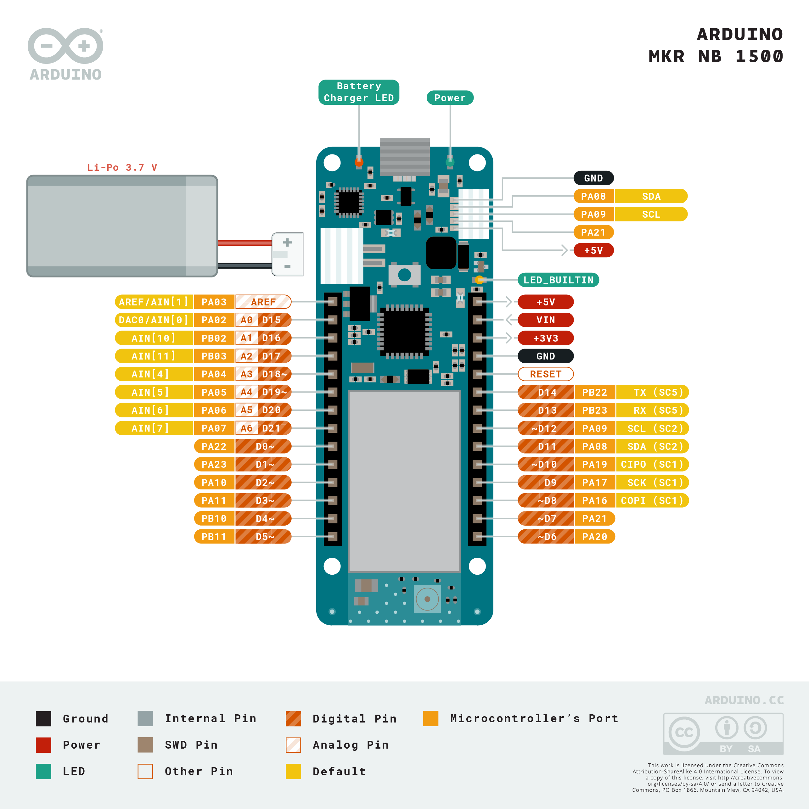
Download the full pinout diagram as PDF here.
Interactive Board Viewer
Additional I2C Port
The MKR NB 1500 has an additional connector meant as an extension of the I2C bus. It's a small form factor 5-pin connector with 1.0 mm pitch. The mechanical details of the connector can be found in the connector's datasheet.
The I2C port, also referred to as the Eslov self-identification port within Arduino, comes with: SDA, SCL, GND, +5V, and an extra digital pin meant to send an alarm to the otherwise plain I2C devices connected to it. The pinout is shown in the following image:
If you are interested in designing your own modules for Arduino boards with this expansion port, the connector we suggest using is code: SHR-05V-S-B, also in the picture.
Learn More
Get Inspired
FAQs
Antenna
When purchased at the Arduino Store, the MKR NB 1500 comes bundled with an antenna that can be attached to the board using the existing micro UFL connector. It is possible to use other antennas using the appropriate pigtail.
When purchasing a different antenna than the one provided (or when making your own), please check that it is tuned for the frequency band in use in the LTE range. Also avoid placing your antenna in parallel to a ground plane like a large metallic surface.
Batteries, Pins and board LEDs
- Battery capacity: Rechargeable Li-Po. Please make sure the battery connector suits your battery. Minimum battery capacity should be 700 mAh, maximum 1500 mAh. The battery-charging chip is programmed with 4 hours of charging time, then it goes into automatic sleep mode. This will limit the amount of charge to max 1400 mAh per charging round. Beware: batteries below 700 mAh should NOT be charged with this board
- Battery connector: The connector is of type JST S2B-PH-SM4-TB(LF)(SN). Mating connector is JST PHR-2.
- Vin: This pin can be used to power the board with a regulated 5V source. If the power is fed through this pin, the USB power source is disconnected. This is the only way you can supply 5V (respect this value) to the board not using USB. This pin is an INPUT.
- 5V: This pin outputs 5V from the board when powered from the USB connector or from the VIN pin of the board. It is unregulated and the voltage is taken directly from the inputs. When powered from battery it supplies around 3.7 V.
- VCC: This pin outputs 3.3V through the on-board voltage regulator. This voltage is the same regardless the power source used (USB, Vin, and battery).
- LED ON: This LED is connected to the 5V input from either USB or VIN. It is not connected to the battery power, thus minimizing the impact on battery usage. It is therefore normal to have the board properly running on battery power without the LED ON being lit.
- Onboard LED: On MKR NB 1500 the onboard LED is connected to D6.
- Charge LED: This LED is driven by the charger chip that monitors the current drawn by the Li-Po battery while charging. Usually it will lit up when the board gets 5V from VIN or USB and the chip starts charging the Li-Po battery connected to the JST connector. Occassionally, this LED will blink at a frequency of about 2Hz. This is caused by any of the following conditions maintained for a long time (over 20 min):
- No battery is connected to JST connector.
- Overdischarged / damaged battery is connected. It can't be recharged.
- A fully charged battery is put through another unnecessary charging cycle.