


Arduino Zero
EsauritoArduino Zero is a simple and powerful 32-bit extension of the platform established by the UNO. This board aims to provide a platform for innovative projects in smart IoT devices, wearable technology, high-tech automation, crazy robotics, and much more.
Overview
Il Zero è un'estensione semplice e potente a 32 bit della piattaforma stabilita dall'UNO. La scheda Zero amplia la famiglia fornendo prestazioni superiori, abilitando una varietà di opportunità progettuali per dispositivi e fungendo da ottimo strumento educativo per apprendere lo sviluppo di applicazioni a 32 bit. Le applicazioni Zero spaziano da dispositivi IoT intelligenti, tecnologia indossabile, automazione ad alta tecnologia, a robotica innovativa. La scheda è alimentata dal microcontrollore SAMD21 di Atmel, che presenta un core ARM® Cortex® M0+ a 32 bit. Una delle sue caratteristiche più importanti è il Debugger Integrato di Atmel (EDBG), che fornisce un'interfaccia di debug completa senza la necessità di hardware aggiuntivo, aumentando significativamente la facilità d'uso per il debug del software. EDBG supporta anche una porta COM virtuale che può essere utilizzata per la programmazione del dispositivo e del bootloader.
Attenzione: A differenza della maggior parte delle schede Arduino, il Zero funziona a 3.3V. La tensione massima che i pin I/O possono tollerare è di 3.3V. Applicare tensioni superiori a 3.3V a qualsiasi pin I/O potrebbe danneggiare la scheda.
La scheda contiene tutto il necessario per supportare il microcontrollore; basta collegarla a un computer con un cavo micro-USB o alimentarla con un adattatore AC-DC o una batteria per iniziare. Il Zero è compatibile con tutte le shield che funzionano a 3.3V e sono conformi al pinout Arduino 1.0.
Puoi trovare le informazioni sulla garanzia della tua scheda qui.
Nota
Le schede Arduino basate su microcontrollori AVR ricevono un reset e riavviano l'esecuzione degli sketch ogni volta che si apre il Monitor Seriale del Software Arduino (IDE). Questo è anche il meccanismo utilizzato per caricare gli sketch su queste schede. Questa scheda è diversa: quando il Zero è collegato tramite la Porta di Programmazione e si apre il Monitor Seriale, la scheda non si resetta automaticamente e lo sketch caricato continua a funzionare. Per riavviare lo sketch è necessario premere il pulsante di reset sulla scheda stessa.
Iniziare
Nella sezione Iniziare, puoi trovare tutte le informazioni necessarie per configurare la tua scheda, utilizzare il Software Arduino (IDE) e iniziare a sperimentare con la programmazione e l'elettronica. Per mantenere il Bootloader del tuo Zero aggiornato, la Procedura di Aggiornamento spiega cosa dovresti fare ogni volta che c'è un nuovo rilascio delle schede Arduino SAMD.
Hai bisogno di aiuto?
- Sul Software sul Forum Arduino
- Sui Progetti sul Forum Arduino
- Sul Prodotto stesso tramite il nostro Servizio Clienti
Tech Specs
| Microcontroller | ATSAMD21G18, 32-Bit ARM® Cortex® M0+ |
| Operating Voltage | 3.3V |
| Digital I/O Pins | 20 |
| PWM Pins | 3, 4, 5, 6, 8, 9, 10, 11, 12, 13 |
| UART | 2 (Native and Programming) |
| Analog Input Pins | 6, 12-bit ADC channels |
| Analog Output Pins | 1, 10-bit DAC |
| External Interrupts | All pins except pin 4 |
| DC Current per I/O Pin | 7 mA |
| Flash Memory | 256 KB |
| SRAM | 32 KB |
| EEPROM | None. See documentation |
| LED_BUILTIN | 13 |
| Clock Speed | 48 MHz |
| Length | 68 mm |
| Width | 53 mm |
| Weight | 12 gr. |
Conformities
Resources for Safety and Products
Informazioni sul produttore
Le informazioni sulla produzione includono l'indirizzo e i dettagli relativi al produttore del prodotto.
Arduino S.r.l.
Via Andrea Appiani, 25
Monza, MB, IT, 20900
https://www.arduino.cc/
Persona Responsabile nell'UE
Un operatore economico con sede nell'UE che garantisce la conformità del prodotto alle normative richieste.
Arduino S.r.l.
Via Andrea Appiani, 25
Monza, MB, IT, 20900
Phone: +39 0113157477
Email: support@arduino.cc
Documentation
OSH: Schematics
The Zero is open-source hardware! You can build your own board using the following files:
EAGLE FILES IN .ZIP SCHEMATICS IN .PDF
Pinout Diagram

Download the full pinout diagram as PDF here.
Interactive Board Viewer
ARM Core Benefits
- 32-bit core that allows operations on 4 byte wide data within a single CPU clock. (For more information see the int type page)
- CPU Clock at 48MHz
- 12 channels DMA controller that can relieve the CPU from doing memory intensive tasks
- 32 bit Real Time Counter (RTC) with clock/calendar function
- 32 bit CRC generator
- Two-channel Inter IC Sound (I2S) interface
- Peripheral Touch Controller (PTC)
For further information about the SAM-D21 microcontroller please refer to the datasheet.
Atmel Embedded Debugger
The Atmel Embedded Debugger (EDBG) implements a SWD interface in order to program the on-board SAMD21 and is also connected to one hardware serial of the microcontroller. This means that the 'Serial' class responds to the programming port of the board. The Zero has been designed in collaboration with ATMEL, and the on-board EDBG can be used through ATMEL Studio to get full access to the microcontroller memories to help debug your code.- VIN. The input voltage to the board when it's using an external power source (as opposed to 5 volts from the USB connection or other regulated power source). You can supply voltage through this pin, or if supplying voltage via the power jack, access it through this pin.
- 5V. This pin outputs a regulated 5V from the regulator on the board. The board can be supplied with power either from the DC power jack (7 - 12V), the USB connector (5V), or the VIN pin of the board (7-12V). Supplying voltage via the 5V or 3.3V pins bypasses the regulator, and can damage your board if it is not sufficiently regulated. We don't advise it.
- 3.3V. A 3.3 volt supply generated by the on-board regulator. Maximum current draw is 800 mA. This regulator also provides power to the SAMD21 microcontroller.
- GND. Ground pins.
- IOREF. This pin on the board provides the voltage reference with which the microcontroller operates. A properly configured shield can read the IOREF pin voltage and select the appropriate power source or enable voltage translators on the outputs for working with the 5V or 3.3V.
Memory
Input and Output
- Serial: 0 (RX) and 1 (TX). Used to receive (RX) and transmit (TX) TTL serial data. These pins are connected to the Serial1 class. The native usb port instead responds to the SerialUSB class
- External Interrupts: available on all the pins except pin 4.
- DAC: A0. Provide a 10bit voltage output with the analogWrite() function.
- PWM: 3, 4, 5, 6, 8, 9, 10, 11, 12, 13. Provide 8-bit PWM output with the analogWrite() function.
- SPI: SS, MOSI, MISO, SCK. Located on the ICSP header only support SPI communication using the SPI library.
- LED: 13. There is a built-in LED driven by digital pin 13. When the pin is HIGH value, the LED is on, when the pin is LOW, it's off.
- Analog Inputs. Six of the 20 general purpose I/O pins on the Zero provide analog input. These are labeled A0 through A5, and each provide up to 12bits of resolution (i.e. 4096 different values). By default they measure from ground to 3.3 volts, though is it possible to change the upper end of their range using the AREF pin and the analogReference() function.
- TWI: SDA pin and SCL pin. Support TWI communication using the Wire library
There are a couple of other pins on the board:
- AREF. Reference voltage for the analog inputs. Used with analogReference().
- Reset. Bring this line LOW to reset the microcontroller. Typically used to add a reset button to shields which block the one on the board.
Programming
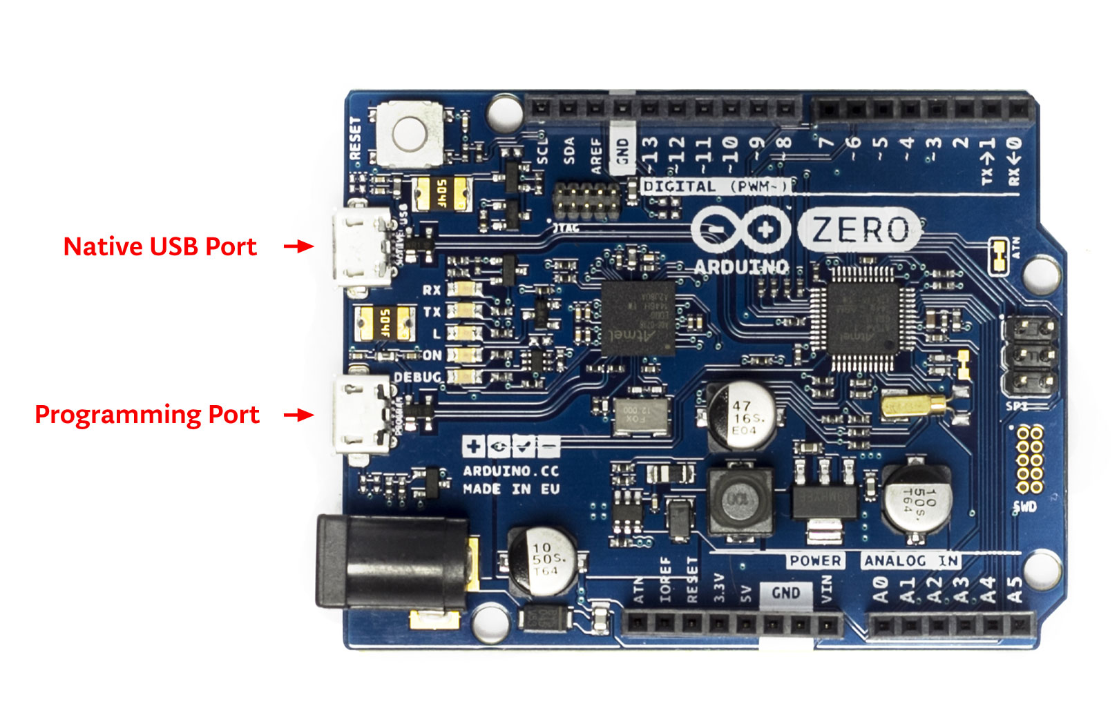
- Programming port: To use this port, select "Arduino/Genuino Zero (Programming Port)" as your board in the Arduino IDE. Connect the Zero's programming port (the one closest to the DC power jack) to your computer. The programming port uses the EDBG as a USB-to-SWD chip.
- Native port: To use this port, select "Arduino/Genuino Zero (Native USB Port)" as your board in the Arduino IDE. The Native USB port is connected directly to the SAMD21. Connect the Zero's Native USB port (the one closest to the reset button) to your computer.
Unlike other Arduino & Genuino boards which use avrdude for uploading, the Zero relies on bossac while the programming port uses openOCD .
JTAG connector for debugging through SWD
Another external debugger can be used by means of the on-board JTAG connector.ICSP Connector used for SPI communication
Here are details of the SPI pins location within the ICSP connector: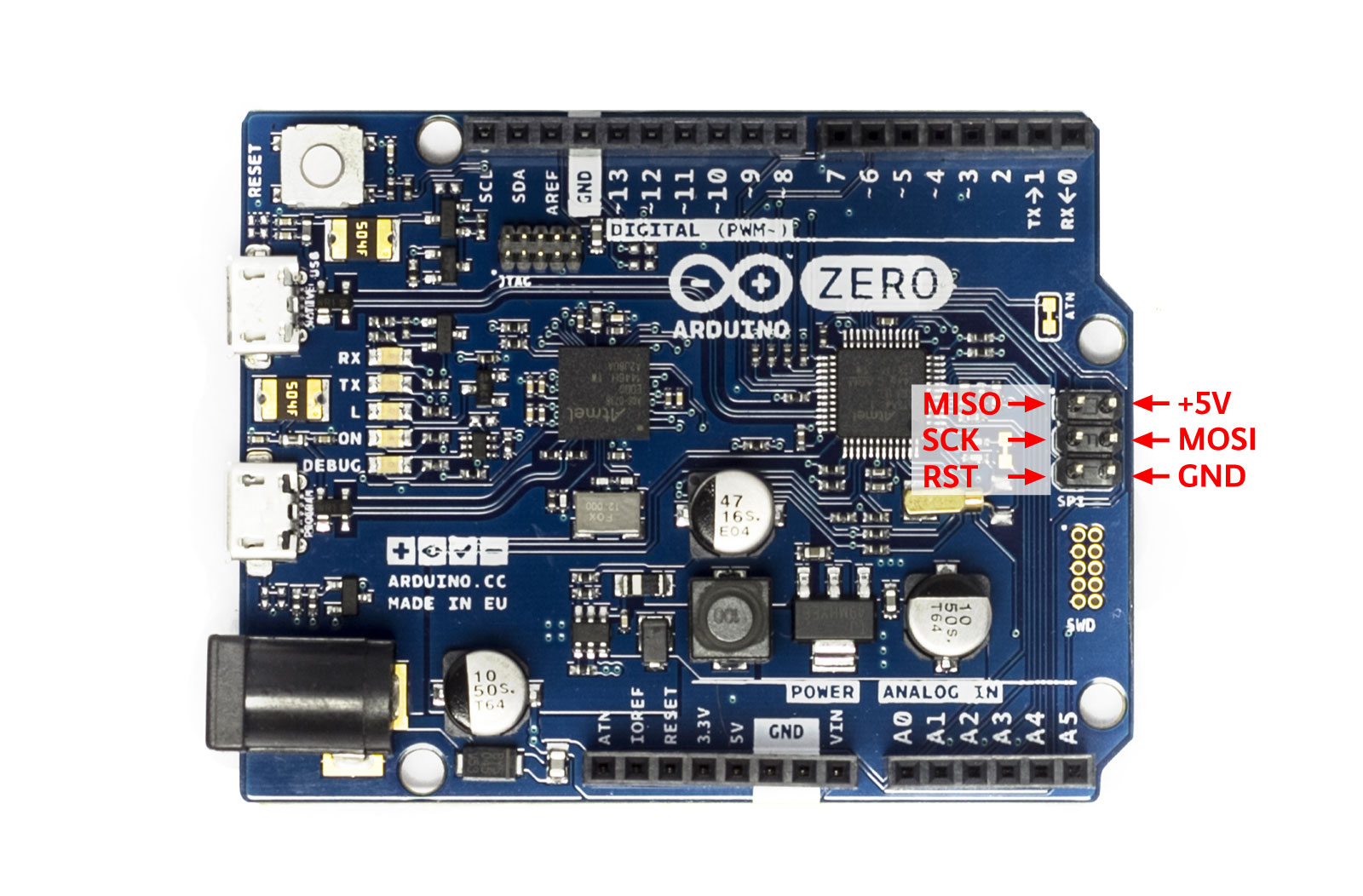
EEPROM
Part of the Flash memory may be used as a non-volatile storage with some limitations, the lifetime of the typical flash memory is about 25K write-cycles, and unlike EEPROM, and it must be erased in pages before writing. The flash memory is erased when you upload a new sketch.Serial ports
- Serial is a hardware serial port internally connected to the EDBG chip and corresponds to the virtual serial port on your computer when you connect the Arduino Zero through the programming USB connector;
- SerialUSB is a virtual USB serial port, which corresponds to the virtual serial port on your computer when you connect the Arduino Zero through the native USB connector.
- Serial1 is the hardware serial port connected to pin 0 and 1, which is free to use to connect to external serial devices.
Burn the Bootloader
- select Tools->Programmer->Atmel EDBG
- select Tools->Board->Arduino/Genuino Zero (Programming Port)
- select Tools->Burn Bootloader