


Arduino MKR ZERO (bus I2S & SD per suono, musica & dati audio digitali)
EsauritoMKR ZERO has an on-board SD connector with dedicated SPI interfaces (SPI1) that allows you to play with MUSIC files with no extra hardware!
Watch out music makers, we’ve got some news for you! We have released two libraries for your enjoyment:
- Arduino Sound library – a simple way to play and analyze audio data using Arduino on SAM D21-based boards.
- I2S library – to use the I2S protocol on SAMD21-based boards. For those who don’t know, I2S (Inter-IC Sound) is an electrical serial bus interface standard for connecting digital audio devices.
Overview
Il MKR ZERO ti offre la potenza di un Zero in un formato più piccolo stabilito dal fattore di forma MKR. La scheda MKR ZERO funge da ottimo strumento educativo per apprendere lo sviluppo di applicazioni a 32 bit. Ha un connettore SD integrato con interfacce SPI dedicate (SPI1) che ti consente di giocare con file MUSICA senza hardware aggiuntivo! La scheda è alimentata dal microcontrollore SAMD21 di Atmel, che presenta un core ARM® Cortex® M0+ a 32 bit.
Attenzione: A differenza della maggior parte delle schede Arduino & Genuino, il MKRZero funziona a 3.3V. La tensione massima che i pin I/O possono tollerare è 3.3V. Applicare tensioni superiori a 3.3V a qualsiasi pin I/O potrebbe danneggiare la scheda.
La scheda contiene tutto il necessario per supportare il microcontrollore; basta collegarla a un computer con un cavo micro-USB o alimentarla con una batteria LiPo. La tensione della batteria può anche essere monitorata poiché esiste una connessione tra la batteria e il convertitore analogico della scheda.
Puoi trovare qui le informazioni sulla garanzia della tua scheda.
Iniziare
Nella sezione Iniziare, puoi trovare tutte le informazioni necessarie per configurare la tua scheda, utilizzare il Software Arduino (IDE) e iniziare a sperimentare con la programmazione e l'elettronica.
Hai bisogno di aiuto?
- Sul Software nel Forum Arduino
- Sui Progetti nel Forum Arduino
- Sul Prodotto stesso tramite il nostro Servizio Clienti
Tech Specs
| Microcontroller | SAMD21 Cortex-M0+ 32bit low power ARM® MCU |
| Board Power Supply (USB/VIN) | 5V |
| Supported Battery(*) | Li-Po single cell, 3.7V, 700mAh minimum |
| DC Current for 3.3V Pin | 600mA |
| DC Current for 5V Pin | 600mA |
| Circuit Operating Voltage | 3.3V |
| Digital I/O Pins | 22 |
| PWM Pins | 12 (0, 1, 2, 3, 4, 5, 6, 7, 8, 10, A3 - or 18 -, A4 -or 19) |
| UART | 1 |
| SPI | 1 |
| I2C | 1 |
| Analog Input Pins | 7 (ADC 8/10/12 bit) |
| Analog Output Pins | 1 (DAC 10 bit) |
| External Interrupts | 10 (0, 1, 4, 5, 6, 7, 8, A1 -or 16-, A2 - or 17) |
| DC Current per I/O Pin | 7 mA |
| Flash Memory | 256 KB |
| Flash Memory for Bootloader | 8 KB |
| SRAM | 32 KB |
| EEPROM | no |
| Clock Speed | 32.768 kHz (RTC), 48 MHz |
| LED_BUILTIN | 32 |
| Full-Speed USB Device and embedded Host |
Conformities
Resources for Safety and Products
Informazioni sul produttore
Le informazioni sulla produzione includono l'indirizzo e i dettagli relativi al produttore del prodotto.
Arduino S.r.l.
Via Andrea Appiani, 25
Monza, MB, IT, 20900
https://www.arduino.cc/
Persona Responsabile nell'UE
Un operatore economico con sede nell'UE che garantisce la conformità del prodotto alle normative richieste.
Arduino S.r.l.
Via Andrea Appiani, 25
Monza, MB, IT, 20900
Phone: +39 0113157477
Email: support@arduino.cc
Documentation
OSH: Schematics
The MKR ZERO is open-source hardware! You can build your own board using the following files:
EAGLE FILES IN .ZIP SCHEMATICS IN .PDF
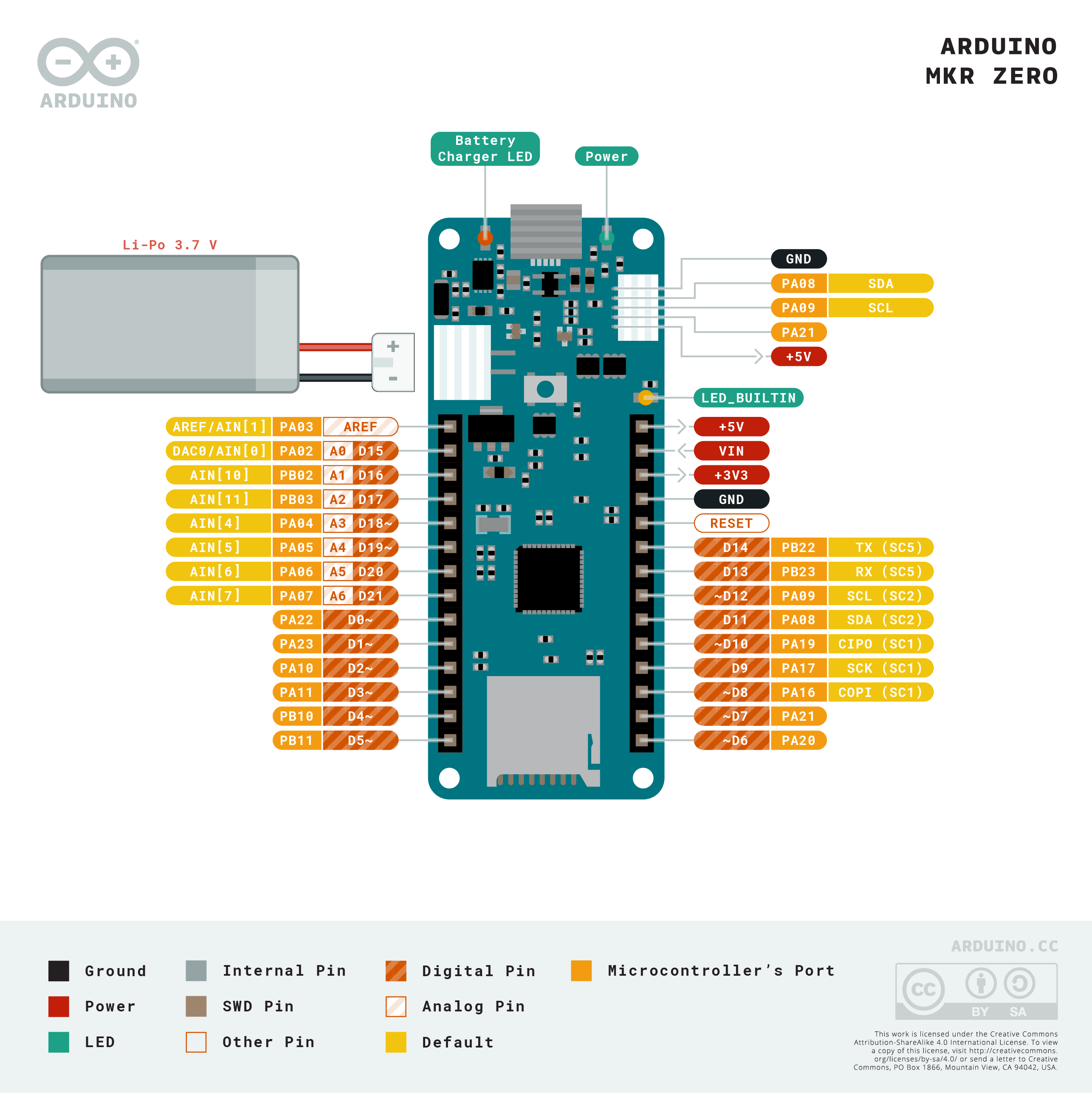
Interactive Board Viewer
Li-Po batteries, Pins, SD and board LEDs
On-board SD
The onboard SD connector allows you to play with files without adding any extra hardware to the board. Furthermore, SD card is driven by a dedicated SPI interface (SPI1) and so any of the pins of the header is busy during SD usage. The SD library automatically recognizes the MKR ZERO and so any modification to the sketch is needed to use it apart from choosing the right SS pin (SDCARD_SS_PIN).
Battery capacity
Li-Po batteries are charged up to 4,2V with a current that is usually half of the nominal capacity (C/2). For Arduino MKR ZERO we use a specialized chip that has a preset charging current of 350mAh. This means that the MINIMUM capacity of the Li-Po battery should be 700 mAh. Smaller cells will be damaged by this current and may overheat, develop internal gasses and explode, setting on fire the surroundings. We strongly recommend that you select a Li-Po battery of at least 700mAh capacity. A bigger cell will take more time to charge, but won't be harmed or overheated. The chip is programmed with 4 hours of charging time, then it goes into automatic sleep mode. This will limit the amount of charge to max 1400 mAh per charging round.
Battery connector
If you want to connect a battery to your MKRZero be sure to search one with female 2 pin JST PHR2 Type connector. Polarity : looking at the board connector pins, polarity is Left = Positive, Right = GND Connector datasheet On the MKRZero, connector is a Male 2pin JST PH Type
Additional I2C Port
The MKRZero has an additional connector meant as an extension of the I2C bus. It's a small form factor 5-pin connector with 1.0mm pitch. The mechanical details of the connector can be found in the connector datasheet. The I2C port in addition to the SDA and SCL signals includes the GND and +5V power rails and a digital pin that might be useful when designing an expansion. The pinout is shown in the following image:

The connector we suggest for this additional I2C Port is the SHR-05V-S-B, also in the picture.
Vin
This pin can be used to power the board with a regulated 5V source. If the power is fed through this pin, the USB power source is disconnected. This is the only way you can supply 5v (range is 5V to maximum 6V) to the board not using USB. This pin is an INPUT.
5V
This pin outputs 5V from the the board when powered from the USB connector or from the VIN pin of the board. It is unregulated and the voltage is taken directly from the inputs. As an OUTPUT, it should not be used as an input pin to power the board.
VCC
This pin outputs 3.3V through the on-board voltage regulator. This voltage is the same regardless the power source used (USB, Vin and Battery).
LED ON
This LED is connected to the 5V input from either USB or VIN. It is not connected to the battery power. This means that it lits up when power is from USB or VIN, but stays off when the board is running on battery power. This maximizes the usage of the energy stored in the battery. It is therefore normal to have the board properly running on battery power without the LED ON being lit.
CHARGE LED
The CHARGE LED on the board is driven by the charger chip that monitors the current drawn by the Li-Po battery while charging. Usually, it will lit up when the board gets 5V from VIN or USB and the chip starts charging the Li-Po battery connected to the JST connector. There are several occasions where this LED will start to blink at a frequency of about 2Hz. This flashing is caused by the following conditions maintained for a long time (from 20 to 70 minutes): - No battery is connected to JST connector. - Overdischarged/damaged battery is connected. It can't be recharged. - A fully charged battery is put through another unnecessary charging cycle. This is done disconnecting and reconnecting either VIN or the battery itself while VIN is connected.
Onboard LED
On MKR ZERO the onboard LED is connected to a dedicated pin (32) and not to 13 as on other boards. It is so suggested to use the LED_BUILTIN define .
(*) Note : DO NOT CONNECT to the male JST connector present on the board anything else than a Li-Po battery whose characteristics are compliant with those indicated above. Please DO NOT POWER VIN with more than 5V.
Learn More
Get Inspired
FAQs
Q: I plugged the board to my PC / MAC but I cannot see the serial port listed on the IDE, I cannot upload sketch to the board!
A: The first thing to try is manually put the CPU into bootloader mode, this is accomplished by pressing quickly twice the reset button (you need a pencil to actually push the button). Another try is to change the USB cable: some micro-USB cables are "power only", you'll see the board powered but no data connection to the PC.
Q: I plugged the board, I can see the serial port but I cannot upload sketch
A: If still on, remove the conductive foam that protects the pins.
Q: What's the pin number of the onboard LED? Pin 13 seems to not work...
A: The LED is connected to a dedicated pin. Use the LED_BUILTIN constant instead of declaring the pin number.
Q: What does the CHRG LED blinking indicate?
A: Indicates that the board is charging the LiPo battery connected to the white JST connector. Please note that the charger use a constant current of 350mA, this means that you must use a LiPo battery with a minimum capacity of 700mAh otherwise you risk unpleasant side-effects like flames and/or explosions.
Q: After some time the Charge LED starts blinking even if no battery is attached to the JST connector
A: The CHARGE LED on the board is driven by the charger chip. This LED starts to blink at a frequency of about 2Hz (slow blink) if a defective or no battery is connected to the JST connector.
Q: I see that A0 is marked as DAC0. There is a DAC on that pin? is usable?
A: Yes, there is a DAC and it's usable, you can control the pin with analogWrite(..).
Q: Which is the VIN range voltage value?
A: VIN Nominal voltage value is 5V, range is from 5V to 6V (6V is the Maximum)
Q: Which is the polarity of the battery?
A: Looking at the connector pins: Left = Positive, Right = GND
Q: How can I use the on-board SD?
A: The on-board is connected to a dedicated SPI interface. The SD library deals with it, so you use the library as usual. Use SD.begin() without specify any pin number, the number will fallback to the right one.
Q: What Vin, 5V and VCC means?
A: Vin. This pin can be used to power the board with a regulated 5V source. If the power is fed through this pin, the USB power source is disconnected. This is the only way you can supply 5v (range is 5V to maximum 6V) to the board not using USB. This pin is an INPUT. 5V. This pin outputs 5V from the board when powered from the USB connector or from the VIN pin of the board. It is unregulated and the voltage is taken directly from the inputs. When powered from the battery it supplies around 3.7 V. As an OUTPUT, it should not be used as an input pin to power the board. VCC. This pin outputs 3.3V through the onboard voltage regulator. This voltage is the same regardless the power source used (USB, Vin and Battery).